Genio 360(P) EVK Demo Requirements
This demonstration kit is very flexible and can be setup in various configurations, with software support for Yocto or Android. However for the purpose of this Quick Start Guide, a specific configuration is chosen with the following conditions:
IoT Yocto software build
Boot from eMMC storage
On-board MIPI-DSI panel used as the display output
Additional Items Needed for Quick Start Guide Demo
To support the demo, the following additional items are needed.
Two USB Cables (USB-A to USB-C)
12V DC power adapter (Φ2.0 DC jack), or a USB Type-C PD power adapter
External PC for loading flash and interacting via command prompt
Setup PC Environment
Install the Genio Tools on your Linux or Windows PC.
Note
The Genio Tools version should be at least 1.7.1. Earlier versions do not recognize the Genio 360 SoC platform. You can check the installed version with genio-flash --version.
Kit Hardware Installation
The Genio 360(P)-EVK ports referenced in this section are shown in the figure below. See Genio 360(P)-EVK for the complete board description.

Port Locations
Select the power source.
The Genio 360(P)-EVK can be powered either by the
DC_INjack with a 12V DC adapter, or by thePD PowerUSB Type-C connector with a USB PD adapter. IoT Yocto does not support using a battery as the power source.Note
The Genio 360(P)-EVK provides a two-way jumper that routes power either through the MT6375 charger or through the RT1715 Type-C PD controller. IoT Yocto v26.0 supports the RT1715 path only, so make sure the jumper is set to RT1715 before powering the board.
Connect a USB cable between the host PC and the connector labeled
UART0, which is the debug console.This requires installation of the FTDI VCP USB driver as outlined in the Setup PC Environment section. If using Windows, open Device Manager and confirm that the driver appears under Ports (COM & LPT) \ USB Serial Port (COMx), where x is the port assigned by your system.
The Genio 360(P)-EVK uses an on-board FTDI FT232RNL bridge on the
UART0USB Type-C connector (CN5101), running at 921600 baud.Connect a second USB cable between the host PC and the connector labeled
USB 3.2 P0, which is the image download port.This requires installation of the Google Android USB driver as outlined in the Setup PC Environment section. If using Windows, open Device Manager and confirm that the driver appears under Android Device \ Android Bootloader Interface.
Further details regarding both USB drivers can be found in the flash trouble-shooting section.
Plug the AC/DC power adapter into the connector selected in the first step.
Connect to the Serial Console
Setup the serial port for viewing debug output and interacting with the kit through a command line interface.
Check Device Manager that the USB COM port appears as a UART device under COM Ports
Configure your installed serial terminal emulator to use the serial port corresponding to the devices UART0 and operating with the baud rate set to 921600.
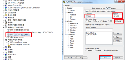
Example with Putty
Use dmesg to determine which USB serial ports have recently been connected:
dmesg | grep tty [299443.861514] usb 2-4.2.1: FTDI USB Serial Device converter now attached to ttyUSB0In this instance, the serial terminal is
ttyUSB0, which will be present under/dev/Connect to the device using a baud rate of
921600, for example, with Picocom:picocom -b 921600 /dev/ttyUSB0
Flash the Software
This guide shows how to “flash” (write) the demo image into the non-volatile flash memory of the main motherboard.
The flashing process is performed through the USB 3.2 P0 connection.
In order to write the on-board storage with Genio Tools, you need to set the Genio SoC in download mode, which allows Genio Tools to transfer a download agent binary to the SRAM of SoC.
The download agent then provides a fastboot interface for subsequent image transfer and storage write operations.
Download the pre-built private board image to your local PC.
Here we select Boot from eMMC storage. The image should be built using
genio-360-evkconfig.Board
Boot Config
Download Link
MD5 Checksum
eMMC boot
894cc8874018505c76a78d71d12a5dbd
Note
The Genio 360(P)-EVK also supports booting from the on-board 16MB SPI NOR flash, which uses the separate
genio-360-evk-norbootimage. This Quick Start Guide uses eMMC boot. Refer to Download for the NOR boot image.Note
Be sure to download the private image as it is required to run the demos in this quick start guide.
Unzip the image.
The image archive contains symbolic links, so on Windows you must extract it with a tool that supports both symbolic links and gzipped tarballs, such as WinRAR run as administrator. Otherwise
partitions.jsonandrity.jsonare missing and genio-flash fails withjson.decoder.JSONDecodeError. See Download Prebuilt Image for details.
Note
Avoid having a long path name by installing to a root folder and shortening the file name if necessary, for example C:\\evk.
Open a Windows cmd window (to enter commands)
Change working folder to the image directory before running the
genio-flashcommands:
cd C:\evk
Flash the image. The default overlays already enable the DSI display, the video codec and the NPU, which is all this Quick Start Guide requires:
genio-flash
Once you see the
Looking for MediaTek SoC matching USB device 0e8d:0003prompt, start the process to boot the board in flash download mode.
Press and keep pressing the
Downloadbutton.Press and release the
RSTbuttonKeep holding the
Downloadbutton until genio-flash printsErasing 'mmc0', then release it.
A typical successful log looks something like this:
Genio Tools: v1.7.1
Yocto Image:
        name:     Rity Demo Image (rity-demo-image)
        distro:   Rity Demo Layer 26.0-release (rity-demo)
        codename: scarthgap
        machine:  genio-360-evk
        overlays: ['apusys.dtbo', 'display-dsi.dtbo', 'video.dtbo']

INFO:aiot:Found FTDI device FT_232R in COM38: {'type': 5, 'id': 67330049, 'description': b'USB <-> Serial Converter', 'serial': b'G3AKLVEL'}
Looking for MediaTek SoC matching USB device 0e8d:0003
Opening COM21 using baudrate=115200
Connected to MediaTek SoC: hw_code[0x8171]
Sending bootstrap to address: 0x201000
Jumping to bootstrap at address 0x201000 in AArch64 mode
erasing mmc0
< waiting for any device >
Erasing 'mmc0'                                     (bootloader) request sz: 0xed2000000, real erase len: 0x0
… (shortened for brevity)
Rebooting                                          OKAY [  0.000s]
Finished. Total time: 0.000s
Note
The above command should be the only one needed to flash the image with the configurations necessary in this Quick Start Guide. Further background and troubleshooting information including different command options are available in Flash Image to Board. A common problem is that the download does not start and simply keeps waiting for the device. More information is available in Missing “Yocto” Device Driver.
Once the kit boots up with the new flash image, debug log messages can be seen through UART0 in the Putty terminal window.
Verify that the desktop boot screen appears on the DSI display of the kit.
Log into board through UART0 interface.
Once board has fully booted, a login prompt is sent across UART0 similar to that shown below.
genio-360p-evk login:
Type
root, then enter, to log in.Note
The login prompt shows
genio-360-evkon a Genio 360 EVK andgenio-360p-evkon a Genio 360P EVK, because the hostname is derived from the SoC detected at boot. Both boards run the same image.Confirm the board is running IoT Yocto v26.0 and detected the expected SoC.
cat /proc/device-tree/model MediaTek Genio 360P EVK cat /etc/os-release | grep PRETTY_NAME PRETTY_NAME="Rity Demo Layer 26.0-release (scarthgap)"
Note
The model string reads
MediaTek Genio 360 EVKon a Genio 360 EVK, for the same reason the login prompt differs. A daily development build reports26.0-devinstead of26.0-release. The prebuilt image linked above is a release build.
GPU Demo
The following sections exercise the GPU and the video codec hardware to confirm that the kit is working correctly.
On IoT Yocto there are several OpenGL ES applications that can be used to
check that the GPU is running and well integrated within the Wayland/Weston
system. This section introduces two GLES
applications: kmscube and weston-simple-egl.
They both use the GPU to render content, but they take different approaches to
creating their graphic windows.
Display a Rotating Cube
kmscube is a simple GLES program that
demonstrates how to drive bare metal graphics without a compositor, using
DRM/KMS,
GBM and
EGL.
Because kmscube creates its own window directly on the display, the Weston
compositor must be stopped first so that no other window system occupies the
display.
Stop the
westonservice.systemctl stop westonConfirm that the desktop disappears and you see only a dark screen on the display.
Launch
kmscubeand confirm that you can see a rotating cube on the display.kmscubekmscubealso prints the GPU and driver information it detected. On Genio 360(P)-EVK the renderer is the Arm Mali-G57:Using display 0xaaaae2ecd3e0 with EGL version 1.5 =================================== EGL information: version: "1.5 Valhall-"r48p0-01eac0"" vendor: "ARM" client extensions: "EGL_EXT_client_extensions EGL_EXT_platform_base ..." display extensions: "EGL_WL_bind_wayland_display ..." =================================== OpenGL ES 2.x information: version: "OpenGL ES 3.2 v1.r48p0-01eac0.c341476615870e1151cf94691d8d0200" shading language version: "OpenGL ES GLSL ES 3.20" vendor: "ARM" renderer: "Mali-G57" extensions: "GL_ARM_rgba8 GL_ARM_mali_shader_binary ..." ===================================
Note
The extension lists and the build hash in the
versionstring are shortened above. Their exact content depends on the GPU driver build.

Screenshot of kmscube
Press
CTRL+Cto stopkmscube, then restart the desktop.systemctl start weston
Display a Rotating Triangle on the Desktop
weston-simple-egl renders a rotating triangle into a Wayland window, so
unlike kmscube it runs on top of the running desktop. It therefore needs the
Wayland environment variables of the running Weston session.
Confirm the
westonservice is running.systemctl is-active weston activeLaunch
weston-simple-egl.export XDG_RUNTIME_DIR=/run export WAYLAND_DISPLAY=wayland-0 weston-simple-egl
Confirm that a window showing a smooth rotating triangle appears on the desktop, then press
CTRL+Cto stop it.

Screenshot of weston-simple-egl
Note
If weston-simple-egl exits with
error: XDG_RUNTIME_DIR is invalid or not set in the environment,
the two environment variables above were not exported in the current shell.
Further details about the GPU, background theory, or troubleshooting can be found in the BSP User Guide - GPU section.
Video Codec Demo
The Genio 360(P)-EVK includes a hardware video encoder and decoder, exposed through the V4L2 stateful codec interface and usable from GStreamer.
Confirm that the hardware codec GStreamer elements are available.
gst-inspect-1.0 | grep v4l2h264
video4linux2:  v4l2h264dec: V4L2 H264 Decoder
video4linux2:  v4l2h264enc: V4L2 H.264 Encoder
Run a pipeline that encodes a generated test pattern to H.264 in hardware, decodes it again in hardware, and displays the result on the desktop.
export XDG_RUNTIME_DIR=/run
export WAYLAND_DISPLAY=wayland-0
gst-launch-1.0 videotestsrc num-buffers=300 ! video/x-raw,width=640,height=480 \
      ! v4l2h264enc ! h264parse ! v4l2h264dec ! videoconvert ! waylandsink
Confirm that the pipeline runs and ends cleanly.
Pipeline is PREROLLED ...
Setting pipeline to PLAYING ...
New clock: GstSystemClock
Got EOS from element "pipeline0".
Setting pipeline to NULL ...
Freeing pipeline ...
Confirm that the test pattern appears in a window on the desktop, as shown in the figure below.

The hardware-encoded and hardware-decoded test pattern on the desktop
Further details about the video codec can be found in the BSP User Guide - Video section.
Note
IoT Yocto v26.0 supports camera sensor interfaces and transferring sensor data via the camera sensor interface, but v26.0 does not support ISP hardware pipeline for Genio 360 SoC. As a result, only OV5640 (YUV sensor) modules are fully usable; IMX258 (raw sensor) is limited to sensor-data dump. Camera capture demo therefore is not covered by this Quick Start Guide. Refer to the BSP User Guide - Camera section and the v26.0 release note for the current camera support status.